Hardware Setup
While this Developer Package is not designed for a specific hardware, it includes ready-to-run samples for the Actions ATS3085S board.
Note
This section is not mandatory if you intend to develop without hardware and only using the SDK simulation environment.
Requirements
Actions ATS3085S/E_DEMO_DVB board, tested with version 1.1,
SEGGER J-Link debug probe,
J-Link Software Pack, tested with v7.94.
Board Overview
Below is a view of the board with key components highlighted.
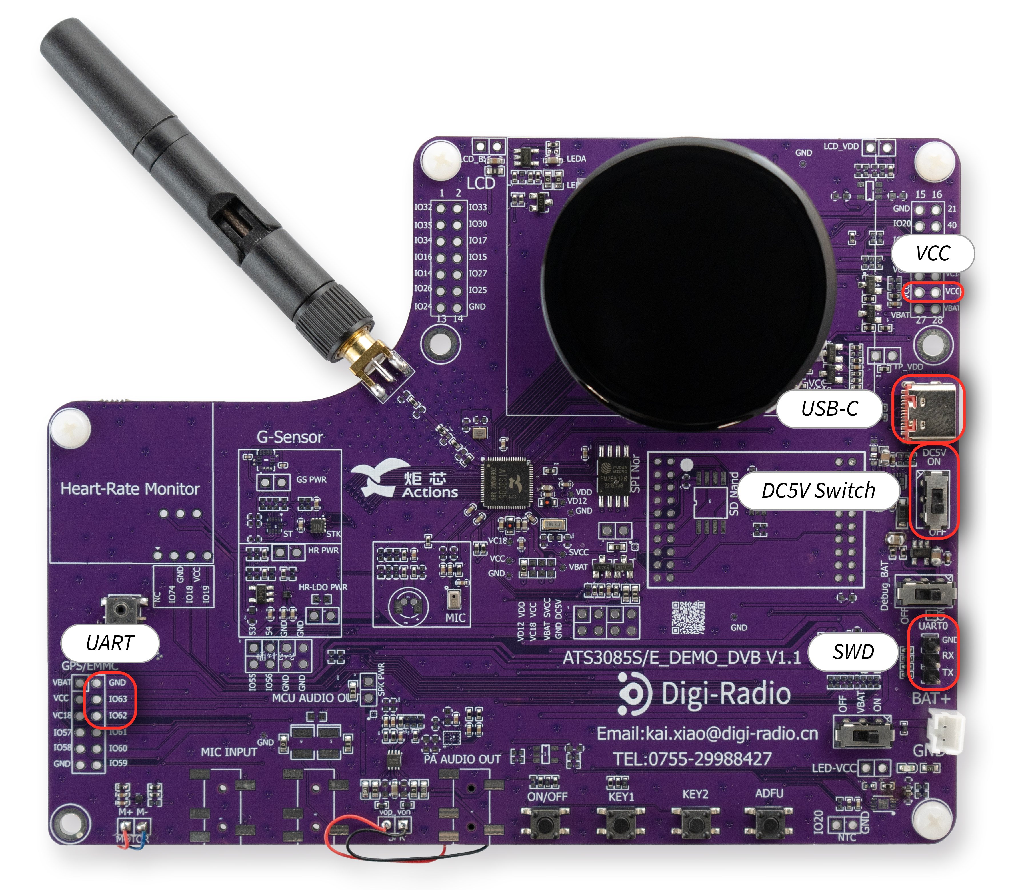
Board Overview
Technical Specifications
Property |
Value |
|---|---|
Name |
ATS3085S/E_DEMO_DVB |
Revision |
V1.1 |
MCU part number |
ATS3085S |
MCU architecture |
ARM Cortex-M33 |
MCU max clock frequency |
192 MHz |
Internal flash size |
0B |
Internal RAM size |
1168 KB |
External flash size |
16 MB |
External RAM size |
8 MB |
Power supply |
5V |
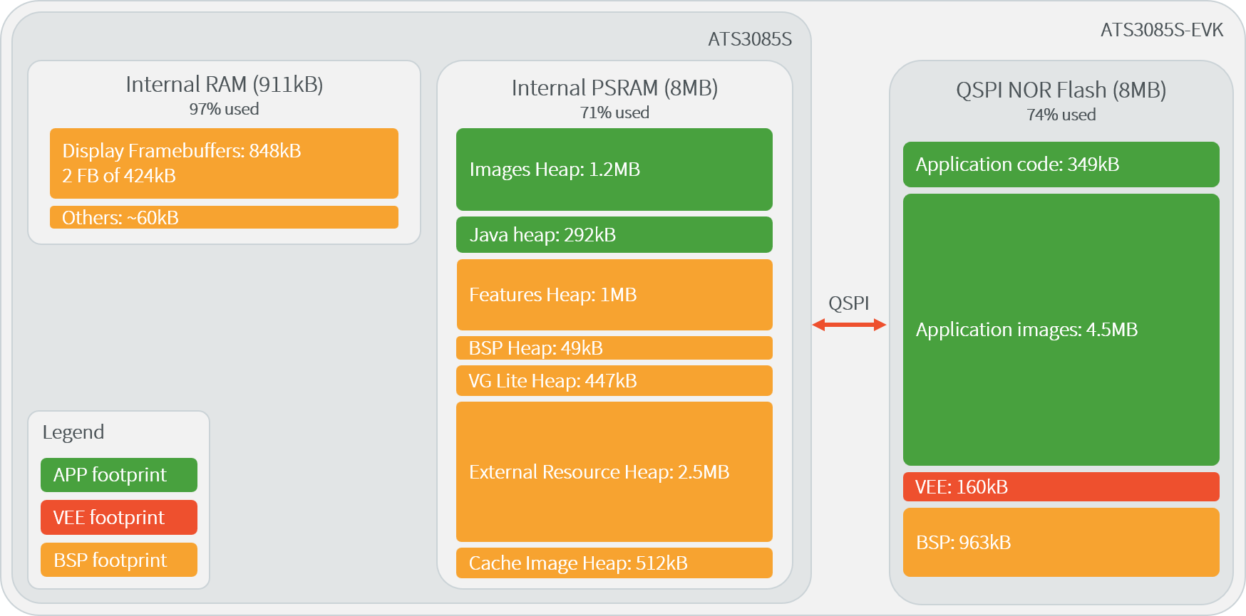
Typical Memory Map for the Actions 3085S board
Power Supply
Connect a USB-C cable to the USB port.
To turn the board on or off, use the “DC5V” switch button.
Programming with J-Link
Connect the J-Link Probe
Connect the J-Link probe to the board (SWD connector and VCC) using wires, as shown in the figure below.
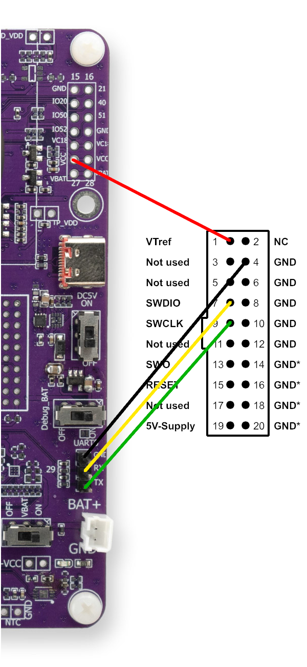
J-Link Connection
Configure J-Link for Actions
The ATS3085S board can be programmed using J-Link Commander.
Follow the instructions below to configure J-Link, based on your operating system:
Press Win + R, type
sysdm.cpl, and hit Enter.Go to the Advanced tab.
Click Environment Variables.
Under System variables, find and select Path, then click Edit.
Click New to add the J-Link installation path (e.g.,
C:\Program Files\SEGGER\JLink_VXXX).Move the new entry up to the top of the list, and click OK.
Finally, add the Actions ATS3085S device to the list of supported J-Link devices by running the following command (replacing
<User>accordingly):xcopy "src\ats3085s-veeport\bsp\tools\JLinkDevices\" "C:\Users\<User>\AppData\Roaming\SEGGER\JLinkDevices" /E /I
From the command line interface:
cp -r src/ats3085s-veeport/bsp/tools/JLinkDevices/ $HOME/.config/SEGGER/JLinkDevices
Note
If the SEGGER/JLinkDevices folder does not exist, it may need to be manually created beforehand.
From the command line interface:
cp -R src/ats3085s-veeport/bsp/tools/JLinkDevices/ $HOME/Library/Application\ Support/SEGGER/JLinkDevices
Note
If the SEGGER/JLinkDevices folder does not exist, it may need to be manually created beforehand.
Logs Output
The VEE Port logs via the UART0 interface of the ATS3085S. To access the logs, connect to the following GPIO pins with a USB-FTDI cable:
GPIO |
Name |
|---|---|
GND |
GND |
GPIO63 |
UART0 TX |
GPIO62 |
UART0 RX |
When the board is connected to a computer, a COM port is automatically assigned. A serial terminal can be used to display the logs from the COM port, using the following parameters:
Baudrate |
Data bits |
Parity bits |
Stop bits |
Flow control |
|---|---|---|---|---|
2000000 |
8 |
None |
1 |
None |